1000 lb Controlled Drop Tester

Design Considerations
-
Military Regulations Compliant
-
Single-axis sled movement
-
Self-supporting structure
-
Max. payload: 1,000 lb
-
Max. impact velocity: 10 ft/s
-
Minimal energy loss
-
Concrete floor anchoring only
-
Low cost & easy maintenance
Design Solution
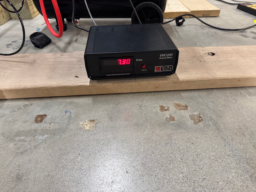
I developed an adjustable ramp system with a low-friction sled to control the velocity of loaded crates during impact testing. By raising or lowering the ramp, the system could vary impact velocity while allowing heavy test articles to be loaded at a safer, more accessible height.
The design incorporated velocity measurement, a reinforced impact backstop, and a self-supporting structure secured to the concrete floor. Cost and maintainability were important considerations throughout development.
Initial Design and Fabrication
The initial design used fiberglass I-beams for their rigidity, strength, and affordability. Pneumatic pistons were installed between the floor and ramp to adjust its height, while two laser light gates measured the sled's velocity as it approached the impact point.
The impact backstop consisted of 4-inch-thick pine boards reinforced with steel beams. I also developed custom 3D-printed sled wheels to reduce friction and simplify replacement. The system was secured using 43 concrete anchors, with mechanical catches incorporated to limit backward movement of the sled and backstop during testing.

Design Evaluation
After six months of operation, a coworker who regularly used the drop tester reported excessive vibration during testing. His observations prompted a closer investigation of the system and the structural issues that had developed.
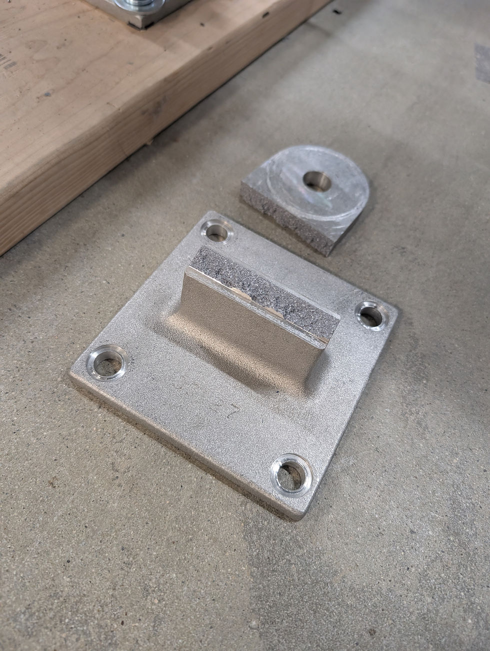
The inspection revealed fractures in a pneumatic support bearing weldment, excessive frame movement, sagging ramp I-beams, and deterioration of the wooden backstop. Examining these failures together, I identified the interaction between the damaged weldment and the excessive vibration as a central issue requiring a broader structural redesign.


To address the excessive vibration and support failures, I redesigned the affected weldments and added two adjustable 45° support legs to reinforce the pneumatic mounting structure. The frame was further strengthened with additional bracing, lock washers, locknuts, and threadlocker to improve connection stability.
The original fiberglass I-beams were replaced with aluminum I-beams, supported by adjustable intermediate columns to address sagging and improve structural stability. The wooden impact backstop was also rebuilt with two additional reinforcement layers, secured using lag bolts to better withstand repeated impacts.
To prevent further sled deformation, I added a 2 × 0.5-inch metal reinforcement strip. All 43 concrete anchors were inspected, with no visible damage identified. Additionally, a daily pre-use inspection procedure was implemented to monitor component condition and identify potential issues before operation.
Structural Redesign & Improvements


